![]() Recently I've been annoyed by
the crappy fan control implementation on a new
motherboard,
accompanied by the fact that the latter did not have connectors for temperature
probes - bad for watercooled builds like the one I was working on. Having the
board in RMA for PCIe issues left me with some time with no proper rig
available, so I thought I'd find me a solution for this.
Recently I've been annoyed by
the crappy fan control implementation on a new
motherboard,
accompanied by the fact that the latter did not have connectors for temperature
probes - bad for watercooled builds like the one I was working on. Having the
board in RMA for PCIe issues left me with some time with no proper rig
available, so I thought I'd find me a solution for this.
In the past I've used two generations of aquaero for which I had written Linux compatible software (aerotools, aerotools-ng). As modern cases rarely have 5.25" bays and Aqua Computer seems to lock down their newer devices using online activation I picked up an old idea: making my very own cross-platform PWM fan controller.
Platform
I wanted the device to be able to work standalone in order to ensure cooling continues to work even when the host firmware crashes so it required an MCU. My choice fell on Arduino as platform to minimize ramp-up-time and benefit from its serial interface and firmware upgrade mechanism that come for free.
Fan Control
Fan control for PWM fans is relatively easy: for pinout you've got GND, 12V,
an RPM signal and a PWM (duty) signal. The RPM signal is driven by a
Hall sensor that generates two LOW
pulses per rotation. So all you need to do is measure the pulse length to
calculate the actual RPM as. The duty signal requires a
PWM of 25 kHz which can
be generated by Atmel MCUs using their on-chip timers. These timers all have
multiple channels (usually three) but pin mapping can get tricky. I also didn't
want to abuse TIMER0 for PWM as that would break delay() and other useful
timing functionality. So I decided to take the Arduino Leonardo (or any other
variant that uses an
ATmega32U4) as it offers
four timers with sufficient pin mapping possibilities.
For setting up the timers I first consulted the
ATMega32U4 Datasheet
but quickly felt lost in the endless depths of timer configuration registers.
Then I found this article by
Sebastian Gillwaldt that contains setup code for TIMER1 and TIMER3. TIMER4
is trickier as that one is a 10bit high speed timer.
This post brought me on the right
track. A TOP value of 240 makes it hit precisely 25 kHz (as can be seen in the
screenshot below).
// Setup Timer4 for 25 kHz PWM

TCCR4A = 0;
TCCR4B = 4;
TCCR4C = 0;
TCCR4D = 0;
PLLFRQ = (PLLFRQ & 0xcf) | 0x30;
OCR4C  = 240;
DDRD   |= 1<<7;
TCCR4C |= 0x09;
Temperature Sensors
The temperature sensors used in watercooling equipment are usually Thermistors so reading them means measuring their resistance and calculating the temperature using the Steinhart-Hart Equation. As the Arduino is not able to measure resistance directly this boils down to creating a Voltage Divider with a known resistor (of the same magnitude) and measuring the fraction of voltage between them. The latter can be done on the Arduino using its analog inputs.
Proof-of-Concept
Having collected all the required parts I thought I'd do a basic proof-of-concept by throwing it all together on a breadboard. As I didn't have an Arduino Leonardo at hand I used my trusty Duemilanove. That one uses an ATmega168 so I couldn't test all timer configurations with it but that's okay for a PoC.
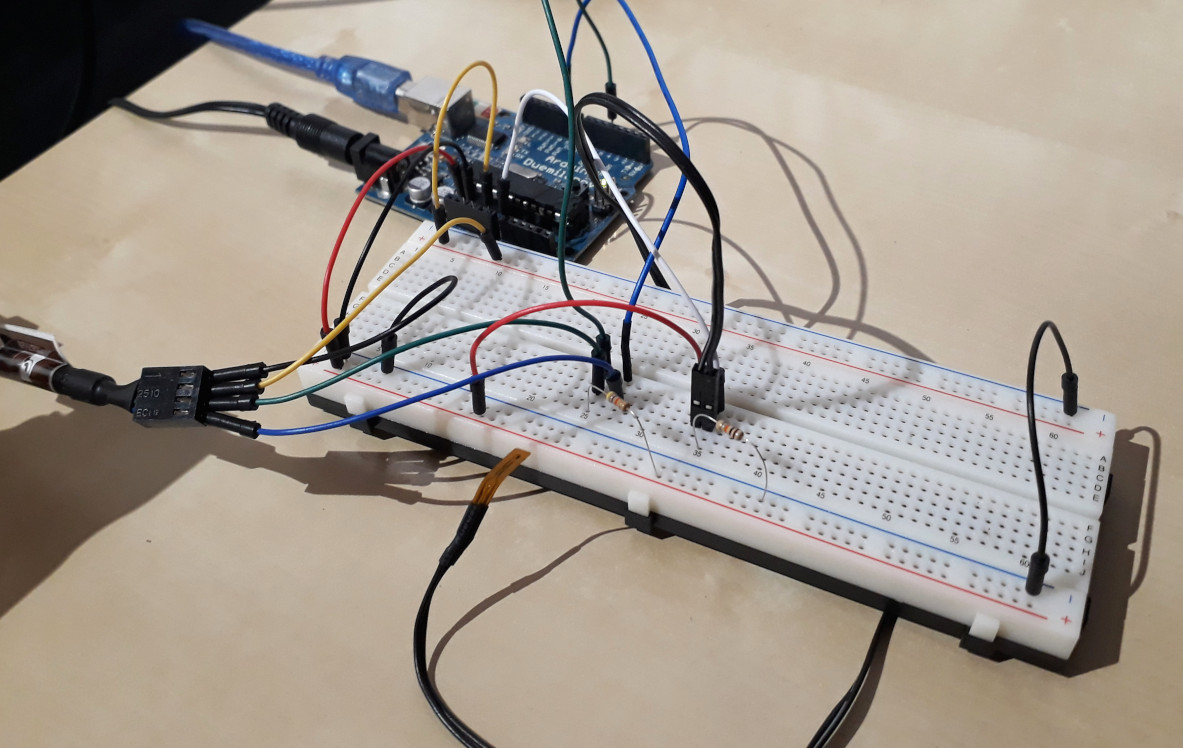
Everything went smooth and I was surprised that the fans I tried would even turn off completely when setting a very low duty cycle, perfect!
Shortly after this first test I received my final target MCU in form of a Paradisetronic Pro Micro which is compatible with the Leonardo. With that one I took the opportunity to make use of a cheap USB logic analyzer I once bought and verified that all PWM channels actually run at 25 kHz.
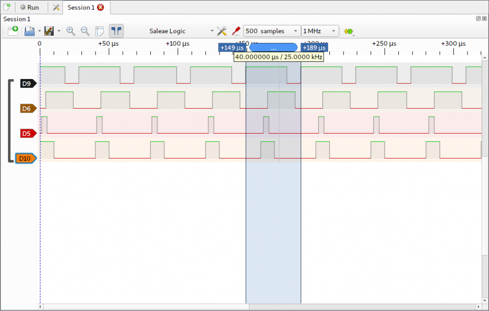
The image shows a screenshot of PulseView) capturing all four PWM channels with different duty cycles.
There was one lesson I needed to learn the hard way: the Pro Micro does not
behave exactly like my Duemilanove when it comes to power supply. It's got a
RAW input pad through which you can feed it unregulated 5-12 V and you can
power it via USB as well. But unlike the Duemilanove it won't disconnect USB
power if you do the former. So when I plugged in USB while having 12 V on RAW
I accidentially fried my Arduino.
Designing a PCB
As I wanted the project to be a bit more professional than the usual duct tape style hacks I decided to design a proper PCB and have it manufactured using online services. This would also give me an insight into the basics of hardware design which I never had before.
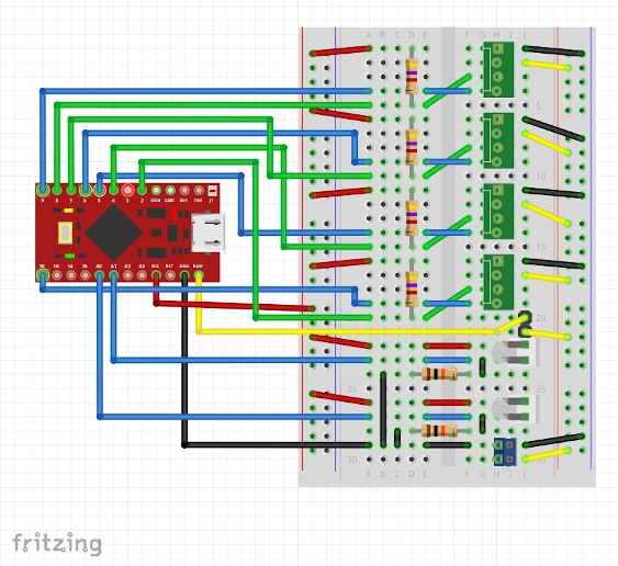
Firing up Fritzing I learned that the default parts library does not contain a Pro Micro. Luckily Hauke Thorenz has covered that gap by providing a model of the Pro Micro version from SparkFun. Trying to integrate that in my Fritzing project I discovered that two pads in the model have wrong X coordinates making them overlap with their neighbour pads and therefore not usable in breadboard view. I fixed that but sadly my pull request has not been accepted (yet).
Having overcome this small issue I started replicating my real-world breadboard setup which finally looked like this:
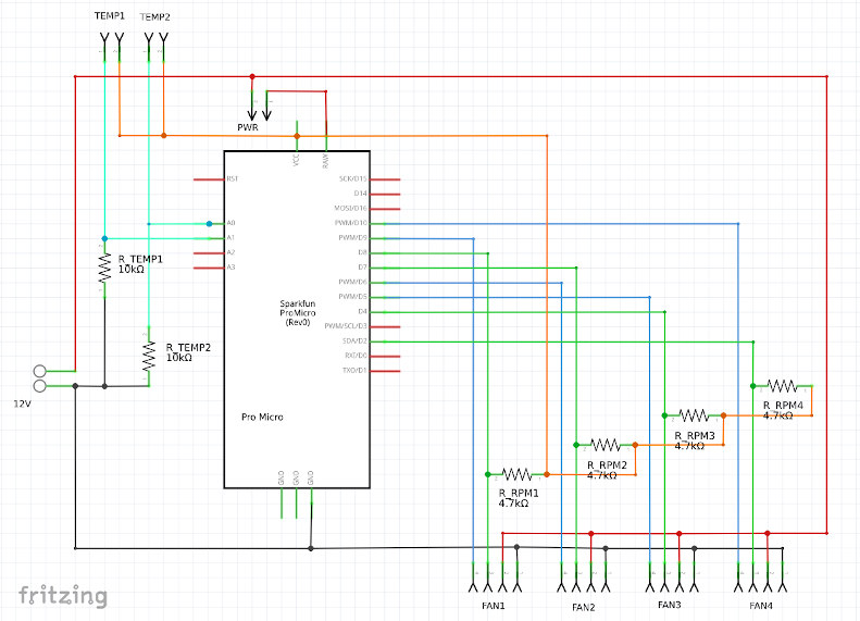
Then I went on with schematics which I tried to keep as clean as possible by using different wire colors (signals vs. power supply).
Then I reached the most interesting (and tricky) part: the actual PCB design. As I wanted the final product to be slim for mounting it on the back side of the motherboard tray I placed the fan headers close to the edge of the board. Using angled headers I could keep the profile as low as the Pro Micro would allow to.
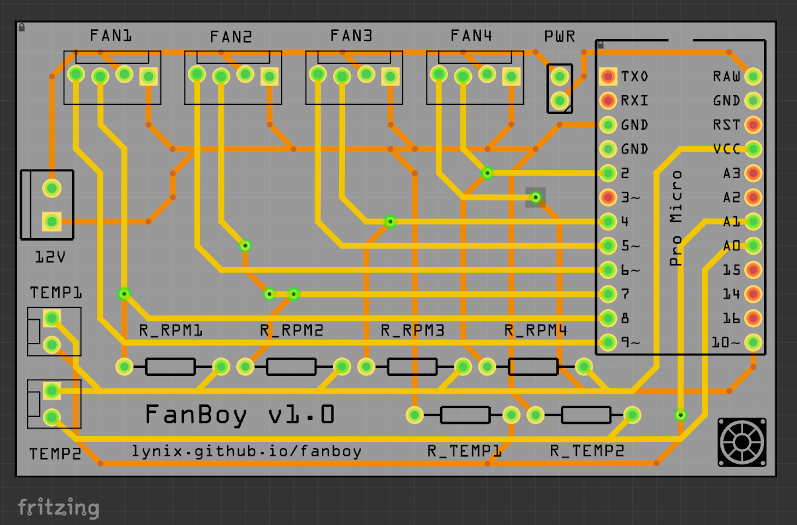
The default wire thickness in Fritzing is 24mil which leads to a maximum power draw of 6 W per channel or 24 W in total, whichever comes first. I thougt this to be enough even for three fans per channel (as with triple radiators).
The logo on the PCB is my own result of playing with Inkscape. I tried to find cliparts of computer fans that are explicitly licensed in an open source compatible way but quickly gave up and just did it myself. Doing some online research for Open Hardware I also learned that it can actually cause you trouble using their logo so I decided not to put it on the board even though it is my aim to keep the entire project open.
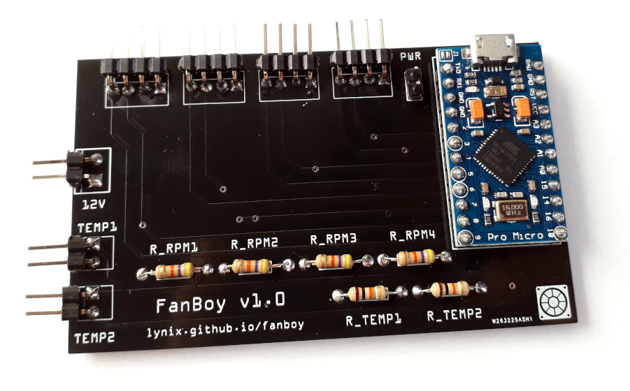
For manifacturing I decided to give PCBWay a try. They give new customers a discount and turned out to have very short turnaround times. Assembly was quite easy, I had enough pin headers and pullup resistors around.
Firmware
Building on top of Arduino offered lots of nice benefits but I was sure right from the start that I wanted to avoid the official Arduino IDE at all costs. I really don't like it - in fact I've never met anyone who does.
So first I tried to do it in plain C without any Arduino core using avr-gcc and avr-libc. While this first seemed to work fine I came to the point where I wanted to have a serial interface to the host for runtime configuration and it turned out that this wouldn't work: the ATmega32U4 has a native USB core and requires the firmware to implement a USB stack for serial communication. While LUFA could provide a solution for this I decided to jump back to Aruino core which includes a USB stack and make use of Arduino-Makefile for painless builds and CI friendliness.
While working on the basic functionality I learned that it takes a considerable
amount of time to measure fan RPM via pulseIn() and that disconnected fans can
cause trouble there: setting a short timeout for that function can make it skip
pulses while using a longer one slows down the application. So instead of
accepting a trade-off I went with longer timeouts and worked around the delay by
implementing auto sensing: disconnected fans are automatically detected on
startup and skipped regarding RPM measurement.
There were lots of little features that were fun to implement like persistent parameter storage in the onboard EEPROM that required a circular storage block implementation to avoid wear on the cells. I stuck with plaintext for serial communication and kept the protocol simple to allow for both human interaction as well as shell script integration or rich client applications (Qt!) in the future.
$ stty -F /dev/ttyACM0 57600 cs8 -cstopb -parenb
$ echo 'set 1 60' > /dev/ttyACM0
$ echo 'status' > /dev/ttyACM0; cat /dev/ttyACM0
Fan 1: 60% @ 1206 rpm
Fan 2: 50% @ 1198 rpm
Fan 3: 15% @ 720 rpm
Fan 4: disconnected

Temp 1: 21.2 °C
Temp 2: disconnected
Future Improvements, GitHub
I'm very happy about how this all has gone so far but the story is anything but over. There are lots of ideas that I have in mind for future improvements. I'm currently re-layouting the PCB to make it fit inside a 2.5 inch drive enclosure and have all connectors on one edge so it can be mounted anywhere an SSD can. A 3D-printable enclosure would be nice as well.
The pin headers work okay but proper fan sockets would be much better. Unfortunately it seems these are very hard to get, especially in an angled version. I was able to get some on AliExpress called KF2510 3+1p, can't wait for them to arrive.
I'll also increase the wire width for the power circuit in order to support water pumps on the PWM channels. Thinking of watercooling equipment it would be nice to have support for flow meters. And maybe an onboard buzzer that could sound an alarm in case a fan stops spinning or the pump fails to work.
So be sure to stay tuned along the ride. I'm sure there will be follow-ups in my blog but in the meantime you can check the official project site on GitHub: